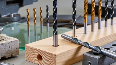
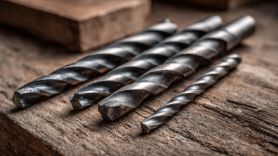
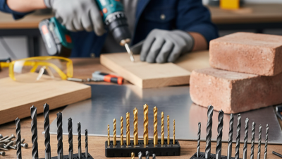
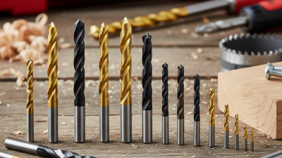
Choosing the right Drill Bits can mean the difference between a clean hole and a scorched edge, a wandering tip, or a broken bit. The best choice depends on more than size. Material, drill type, coating, point angle, and cutting speed all matter. A bit suited to soft pine may struggle in stainless steel. One designed for masonry needs a hammer-action drill and a different tip. Small details count: a pilot hole can steady a bit, while too much pressure can overheat it.
Machining educator John Saunders is known for practical shop-floor instruction. A useful principle consistent with that approach is: “Match the bit to the material, then let the tool do the cutting.” This is an editorial paraphrase, not a verbatim quotation. It captures a habit worth keeping: check the workpiece, read the bit’s specifications, and test carefully when conditions are unfamiliar. Even experienced users can misjudge a coated surface or a dull edge. That happens. This guide’s seven tips will help you compare bit materials, choose the right point and coating, and avoid common mistakes. It will also explain when a general-purpose bit is enough—and when a specialized option is the safer, cleaner choice.
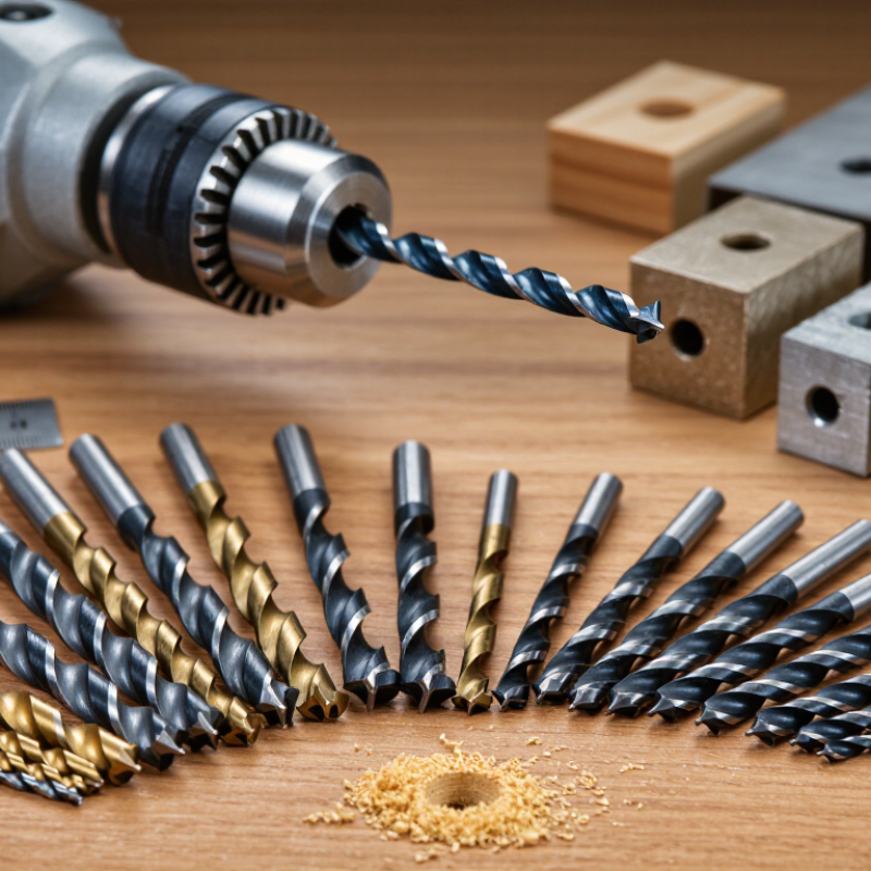
Identify the workpiece before choosing a bit. M42 high-speed steel contains 7.75–8.75% cobalt, which helps it retain hardness when cutting generates heat. That makes M42 a practical choice for stainless steel and many alloy steels. A useful clue, not a promise. The material, bit geometry, and cutting setup still affect results.
Cobalt is part of the steel, not a surface coating, so the bit can be resharpened. For example, drilling a stainless plate with a handheld drill can quickly overheat the tip. Use a slower speed, steady pressure, and cutting fluid where appropriate. Clear chips often, too. A hot, discolored tip is a sign to pause and reassess rather than push harder.
M42 is not automatically the best choice for every job. Softer wood or plastic may call for a different bit geometry, while masonry needs a purpose-made bit. Match the point and diameter to the task, and secure the workpiece firmly. I would not judge performance by cobalt content alone; a dull edge or poor alignment can still make a capable bit wander or wear prematurely.
The point angle changes how a drill bit enters the material. A 118° point is a dependable general-purpose choice for common drilling in wood, plastic, and softer metals. Its broader, more gradual point can work well when the material is forgiving and the hole does not need especially precise starting control. Keep the bit square to the surface; even a good geometry can wander if the drill tilts. That matters.
A 135° split-point bit has a flatter tip and split cutting edges that help it start with less walking, especially on harder metals such as stainless steel. It often needs less pressure to begin cutting, but it is not a cure for poor setup. Clamp the work securely, use a suitable speed, and add cutting fluid when the material and operation call for it. Not always. A split point may cost more, and in soft material its advantage can be modest. I have found that the “best” angle depends on the job: a clean center mark, sharp edges, and steady feed can matter as much as the number stamped on the package. If the hole location is critical, test on scrap first. That small check can prevent an off-center hole in the finished piece.
ANSI B94.11M provides dimensional guidance for standard twist drills, helping you compare bit diameter and shank dimensions before buying or setting up a tool. Check the size marking against a reliable standard chart; fractional, letter, number, and metric sizes are not interchangeable. A near match can still leave a hole too loose or a bit that binds.
Match the shank to the drill’s chuck or spindle, not just the cutting diameter. Straight shanks must fit within the chuck’s clamping range and seat securely. Taper shanks need a compatible socket and should sit firmly without wobbling. Never force a shank into a chuck that cannot grip it properly.
Small mismatch, real trouble.
Check both the bit specification and the tool manual.
For repeat work, measure the bit with calipers and inspect the shank for damage or burrs. A printed size may not tell the whole story, especially with worn bits or older stock. Standards help, but they cannot correct a poor fit or worn chuck. I’d still verify the setup with a test hole in scrap material; it takes a minute and can reveal an error before it matters.
Flute design determines how easily chips leave the hole. For general drilling in steel, a standard spiral flute usually clears short chips well. When drilling deeper holes, a parabolic flute offers more space for chips to travel. Watch the chips. Long ribbons that pack around the bit can signal poor evacuation, excessive feed, or a flute choice that does not suit the job. Slow down, clear the hole when needed, and check whether the chips come out freely. A small change in feed can matter.
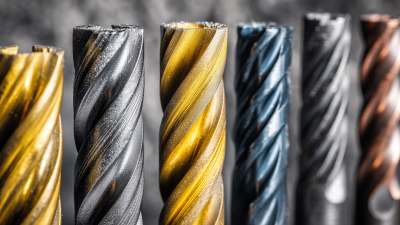
Coatings help manage friction and heat, but they are not a substitute for the right bit geometry. A heat-resistant coating can be useful in demanding applications, while a low-friction surface may help chips slide along the flutes. Match the coating to the workpiece and cutting conditions, including whether coolant is used. Check the manufacturer’s guidance for the bit and material. It is easy to overvalue a coating; chip shape and hole quality deserve attention too. If the bit squeals, discolors, or leaves a rough hole, pause and inspect the setup. Sometimes the coating is fine. The feed, speed, or chip clearance may need a second look.
How flute count affects available chip space
Fewer flutes generally leave more room for chips to travel, which can help with chip evacuation—especially in deep holes or gummy materials. This is qualitative guidance, not measured test data; actual performance depends on bit geometry, workpiece material, feed, speed, and coolant. Choose a suitable coating to help manage heat, following the toolmaker’s recommendations for your application.
Set drill speed and feed from the bit maker’s table for the exact workpiece material. A setting for mild steel may overheat a bit in stainless steel, even when both pieces look similar. Check the stated bit type, diameter, coating, and coolant conditions too. Small details matter. The Machinery’s Handbook, 31st edition, gives the standard inch-unit speed calculation: RPM = cutting speed in surface feet per minute × 3.82 ÷ bit diameter in inches. For example, a table value of 80 surface feet per minute gives about 1,222 RPM for a ¼-inch bit. That number is illustrative, not a universal setting.
Use the matching feed value from the same technical data, then calculate feed rate as RPM × feed per revolution. If the table specifies 0.004 inch per revolution, the example runs at roughly 4.9 inches per minute. Start within the maker’s range, keep the bit straight, and listen for squealing or watch for dark chips. Both can signal excess heat or poor cutting conditions. A pilot hole can change the result, so follow the bit-specific instructions. I still recheck the table when the stock changes; generic charts are convenient, but sometimes misleading. If the bit chatters, stop and inspect the setup rather than forcing it.